Electrickery

A collection of stuff - original and modified

Aprilia wasn't the only culprit when it came to Ducati electrics, Ducati Elettrotecnica also played a part.
If your wiring loom and fuse box is original it would pay to coat all your connections in dielectric grease. This grease is expensive and could save your bacon. It's properties provide waterproofing and prevent oxidation of the connections - a smear is all that's required.
This will save your fusebox from meltdown. It is worth resoldering all the terminal ends on the wiring loom. Clean with flux before resoldering.

1972 750GT tooltray, fusebox and detail

 Original apart from one wiring terminal end. Click on any image.
If you still have an original fuse box it is worth preserving. On removal, you will notice the terminal pieces are held together with a rivet. Clean the terminal pices with a brass or stainless brush, then coat the teminal base joiner with epoxy adhesive. This will help hold together the connection and prevent poor conduction. If you have the skill make a rivet setter and reset the rivet before using the epoxy.

1972 750GT regulator - original and replacement

First two pics show the original regulator, they were reliable given the marginal alternator output of 150watts at 4500rpm.
Third pic is of Shindengen ( SH-548 ) 27amp regulator on a 6mm aluminium heatsink. Yes, there is a 280watt alternator stator and rotor lurking within ( 13.2v at the battery @ 1200rpm ).
Details of that modification here. These replacement regulators will marginally help an original system. The regulator is mounted in the original position under the left sidecover.

1972 Ignition Coil and Leads


Original coil detail. Note the rubber seal and threaded plug for securing lead to ignition coil.
Spark plug cap is original  KLG. These original coils were very ordinary performers.

Replacement Coils and Ignition Leads

These coils are el cheapo Emgo, generally known as 12V Lucas replacement coils, same diameter and length as the originals. Primary resistance is 4.0 ohms, no ballast resistor. Triggered by Dyna S electronic ignition (DS4-1). Leads are available from Mdina Italia in both the red of the '72 model and the green of the '73 model. They are not strictly correct but look very close to the original and better than black (which was on the '74 models only)

Ignition Points and Condensers

The original points and condensers were made by  Ducati Elettrotechnica of excellent quality. These items last a long time with maintenance and adjustment. The condensers were well matched. A small amount of light grease on the points cam rubbing block  reduces wear on the points cam arm.
When fitting new condensers and points you were expected to crimp or solder the wires to the terminals. The genuine parts are also marked Ducati.
Click on each image below for a larger view
dist wiring condenser points

This engine is fitted with a Dyna S electronic ignition, the condensers have been replaced with machined aluminium buttons. When I get some spare condensers they will be replaced to restore the original appearance.
The Dyna S system is a set and forget item, providing reliable spark and long life. They do have an increased current draw over the original points. There are fitting and testing instructions below.

Aprilia Switches and Others

hilo blink
Aprilia switches were used on the bars until late in '74. The high/low beam and horn were located on the left side.The directional blinker and headlamp high beam flasher were located on the right bar. In practice this is an almost impossible and dangerous arrangement. On my bike they have changed sides for ease of use. Ergonomics weren't thought of until much later.
blinkback The right switch mounting plate is fixed to the front  master cylinder studs, the threads of the nuts differ depending on whether the bike is fitted with Lockheed ( imperial ) or Scarab ( metric ) brakes. There is also a small rubber seal to protect the wiring through the plate.

The ignition switch is located on the left side at the joining of the frame tubes. There is a rubber boot at the rear to protect the wiring. There are three terminals on the rear of the switch Click on the keys for a look at an original set of keys. The keyring ( Made in Milan - the Italian hub of styling ! ) has been with the bike since new in 1972, supplied as an accessory by Frasers the Australian distributor.
The three position light control switch located on the dash between the instruments had functions for off, parking lamps and headlamp. There is a second variation in the switch grip, the later version having a plastic coined and shaped grip with Aprilia written on the side.
The rear brake lamp switch was made by Burgess in England.
Click on the image for a view of the switch front and rear.
The switch can be disassembled carefully, the contacts cleaned, then a smear of dielectric grease on the contacts and assemble.

Tail Lamp

Two types of CEV tail lamps were fitted for the Australian and European market.
From 1971 to mid '72 ( eng. # 750 500 )  the CEV 9313 a large full metal body type. These early lamps were also fitted to Laverda and Moto Guzzi models of the period.
From mid '72 until the end of production in '74 a smaller CEV with full lens is fitted.
There is a detail view of the CEV brackets in the Cycle Parts section.

Horn

The horn fitted to the '72 model was a CEV12v. There is no separate relay.
Later bikes were fitted with either a single ( Alto ) or dual ( one each of Alto and Basso ) Voxbell units. The single horn units were reasonably loud. They can be deriveted and rechromed as necessary.
On the rear of the body is an adjusting screw and locknut which is used to adjust the tone of the horn if necessary.

Headlamp

Aprilia 
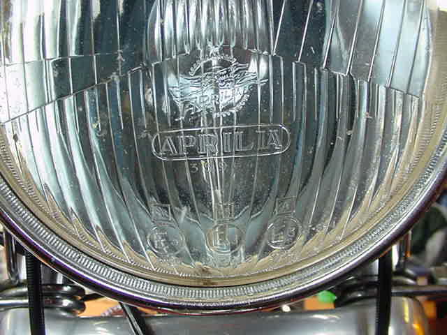
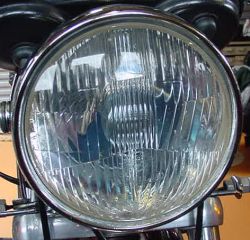
headlamps were fitted to all the 750GT models. For the European and Australian markets they were of a semi sealed beam type. The beam was adjustable via screws in the front of the rim.
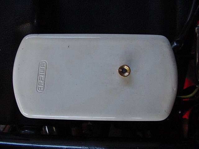
hl Click 
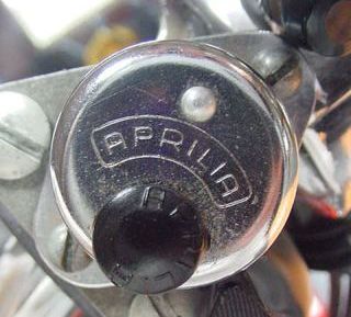
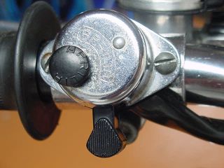
on the headlamp front image for a close up of the Aprilia greyhound logo.One of the headlamp beam adjuster screws is visible in the side view. This lamp has been replated and the mounting ears which were originally riveted on were removed and replaced with button head screws.

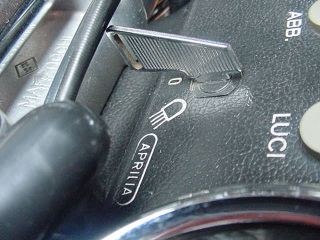
Indicators or Blinkers

Indicators came in the crate with the bike and were at the time in some markets optional. Some owners still have them. They were made by Aprilia. 
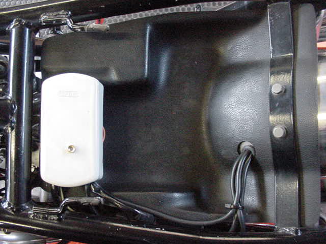
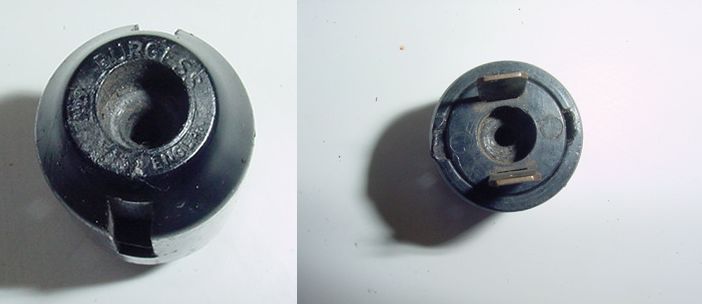
Inside the headlamp was a simple 2 wire terminal block for the front 
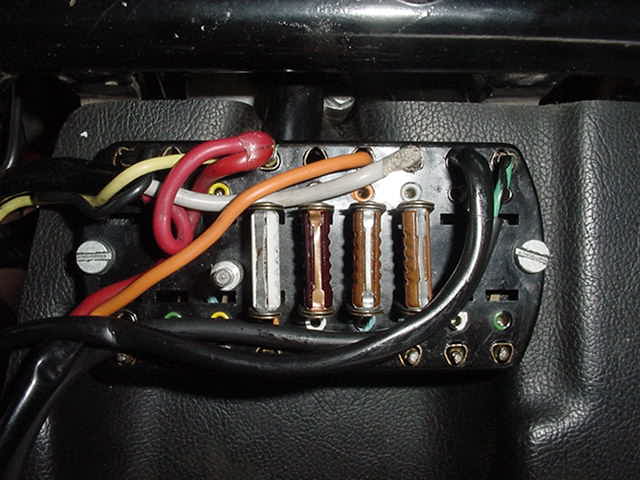
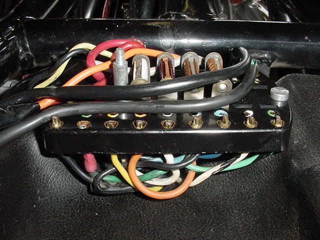
pair. The rear pair were accommodated by way of colour coded positions in the fuse box, fitting is a simple affair. Being made of cast metal then chromed they are heavy and can fracture the rear mount wire. The US models had a different rear mount and the '72 model bikes had a slightly different front mounting wire to the later models.


return to home